
 Lumistrips EN
 Lumistrips UK
 Lumistrips ES
 Lumistrips ITA
LED Grow Lights for Vertical Farms: Module Design Considerations
-
 By
Lumistrips LED Professional
By
Lumistrips LED Professional
- May 11, 2026
Part of the Lumistrips Horticulture LED Series — a technical resource for growers, vertical farm operators, and horticultural engineers.
Why Vertical Farms Demand a Different Approach to LED Module Design
Vertical farming, the practice of growing crops in vertically stacked layers inside controlled-environment buildings, has grown rapidly from a research concept into a commercially significant segment of controlled-environment agriculture. The appeal is well-founded: vertical farms eliminate the dependency on arable land, enable year-round production regardless of season or latitude, reduce water consumption by 70–95% compared to field cultivation, and allow crop cycles to be optimized for maximum throughput rather than seasonal availability.
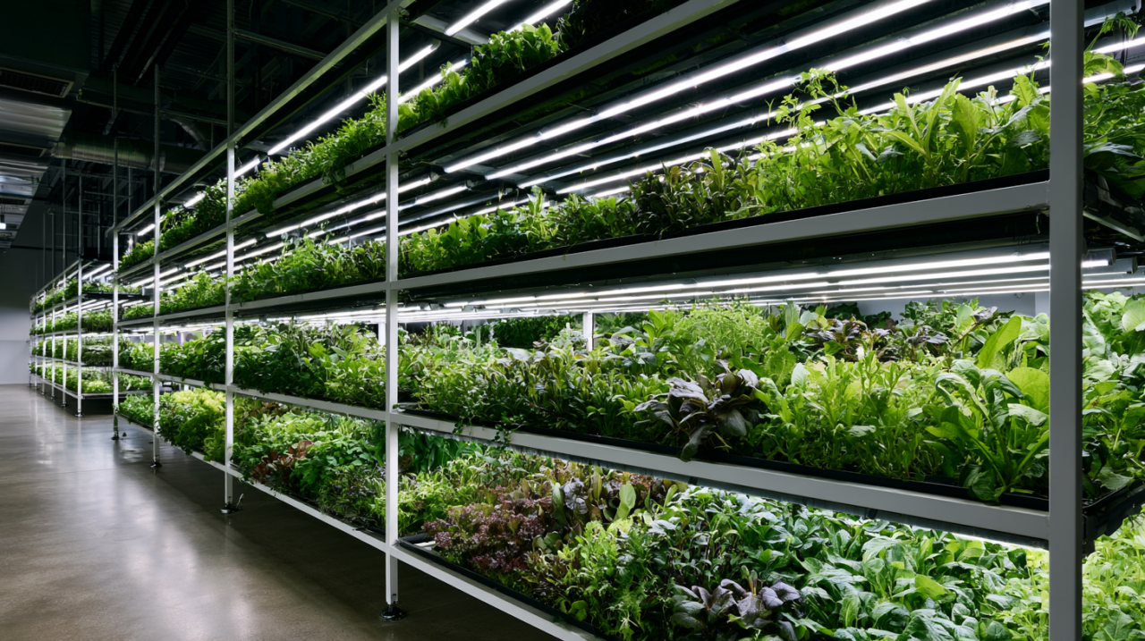 A commercial vertical farm where LED lighting is the only light source. Electricity for lighting typically represents 25–30% of total operating costs — making every LED module design decision a direct economic variable.
But the economics of vertical farming are governed by a single dominant variable that does not apply to the same extent in conventional greenhouse operations: electricity cost for artificial lighting. In a greenhouse, natural light supplements the artificial system which means the LED is an add-on to a solar resource. In a vertical farm, the LED is the only light source. Lighting typically represents 25–30% of total operating costs in vertical farms, with some analyses placing electricity cost as high as 70% of all energy end use in controlled environment agriculture applications. Every engineering decision in a vertical farm LED module, such as spectrum, efficacy, lifetime, module format, mounting distance, inter-tier spacing, and control strategy, has a direct and computable impact on the economics of production.
This has consequences for how LED modules must be specified for vertical farm applications. The criteria that govern module design in a greenhouse supplemental lighting context, adequate PPFD at canopy level, reasonable fixture count, and acceptable TCO remain relevant, but they are joined by constraints that are specific to the vertical farm architecture: the constraint of fixed inter-tier spacing, the constraint of close mounting distance, the critical importance of energy-use efficiency at the crop level, and the requirement for complete uniformity across a growing tray that may be only 0.3–0.6 m from the LED module surface.
This article covers the design considerations that distinguish a vertical farm LED module specification from a greenhouse supplemental lighting specification, drawing on Lumistrips' database of LED lighting systems for plant growth and the research literature on vertical farming light optimization.
Understanding the Vertical Farm Architecture
The Multi-Tier Rack System
The defining structural feature of a vertical farm is the multi-tier growing rack, a framework of shelves stacked vertically, each housing a growing tray with an LED lighting module immediately above. Tier heights vary by crop and facility design, but typical configurations range from 0.40 m to 0.75 m of clear height between the growing surface and the underside of the tier above, with the LED module mounted within that clearance. This places the LED surface 0.15–0.40 m above the plant canopy, depending on the growth stage of the crop and the module mounting position within the tier.
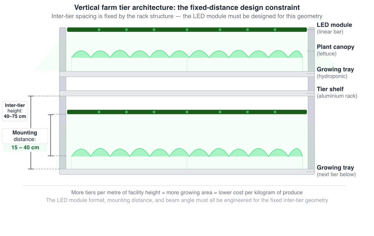 Vertical farm tier architecture: the fixed-distance design constraint. Unlike greenhouse overhead lighting, where mounting height can be adjusted, the LED module in a vertical farm rack must be engineered for a geometry determined by the rack structure:i nter-tier height, growing tray depth, and canopy height at harvest together define the mounting distance the optical design must solve for.
The consequences of this architecture for LED module design are profound. At a 0.2–0.4 m mounting distance, the optical dynamics are fundamentally different from a greenhouse overhead luminaire at 3–8 m. The PPFD distribution at canopy level is governed by the near-field optical behavior of the LED package and any secondary optic, not by the far-field emission pattern that dominates at greenhouse mounting heights. Hot spots and edge effects that are averaged out over a long throw distance in a greenhouse become visible and agronomically significant at vertical farm mounting distances. The entire PPFD uniformity problem must be solved in the optical near-field, which demands a different set of optical tools and design calculations.
A second consequence is heat management. At very close mounting distances, radiant heat from the LED module affects the microclimate of the growing tier below, a concern that does not arise in overhead greenhouse lighting where mounting height creates a large thermal buffer. LED modules for close-canopy vertical farm applications must be thermally managed to minimize radiant heat emission toward the plant canopy, not just to protect the LED components themselves.
PPFD and Distance: The Inverse Square Law
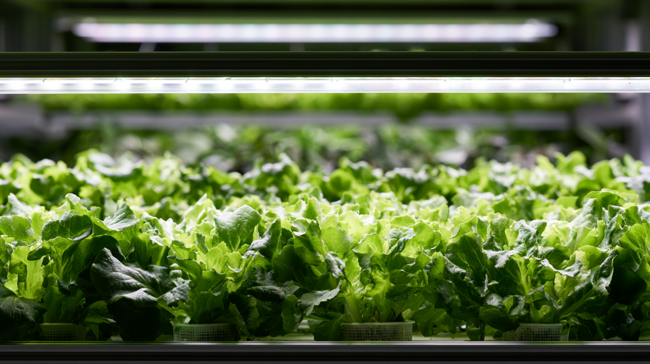 At 15–40 cm mounting distance, the optical near-field behaviour of LED modules dominates PPFD distribution — fundamentally different from greenhouse overhead luminaires at 3–8 m. Standard dome-lens LEDs can create hot spots at these distances without secondary optics or purpose-designed close-canopy beam profiles.
When light travels from a point source through space, it spreads outward in all directions. The same total number of photons that pass through 1 m² at a distance of 1 m must pass through 4 m² at a distance of 2 m — because the area a cone of light covers grows with the square of the distance. The photon density (PPFD) therefore falls proportionally.
Example
If a LED module delivers 300 µmol m⁻² s⁻¹ at 30 cm mounting distance:
| Distance | PPFD | Calculation |
|---|---|---|
| 15 cm | 1,200 µmol m⁻² s⁻¹ | 300 × (30/15)² = 300 × 4 |
| 30 cm | 300 µmol m⁻² s⁻¹ | — baseline — |
| 60 cm | 75 µmol m⁻² s⁻¹ | 300 × (30/60)² = 300 × 0.25 |
| 120 cm | 18.75 µmol m⁻² s⁻¹ | 300 × (30/120)² = 300 × 0.0625 |
Halving the distance quadruples the PPFD. Doubling the distance reduces PPFD to one quarter.
Why This Matters in Practice
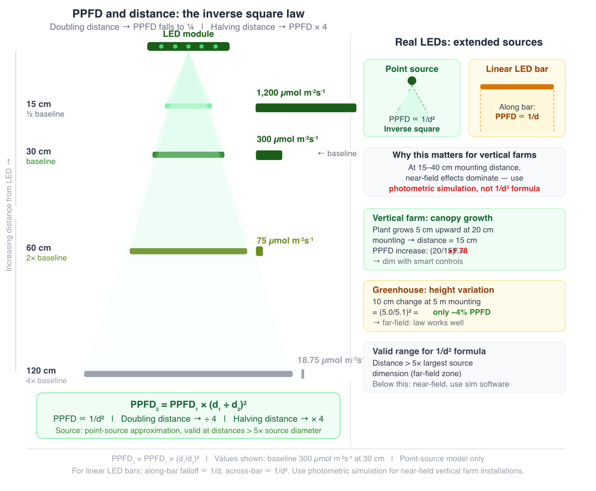 PPFD and distance: the inverse square law. Halving the mounting distance quadruples PPFD; doubling it reduces PPFD to one quarter. At vertical farm mounting distances of 15–40 cm, the near-field behavior of extended LED sources means the simple 1/d² formula underestimates real variation, thus photometric simulation software is required for accurate uniformity design at these distances.
In vertical farms, where mounting distance is 15–40 cm and fixed by the rack structure, this relationship is critically important in two directions:
- A crop that grows from seedling to full canopy height reduces the distance to the LED bar, which increases PPFD nonlinearly. A crop that grows 5 cm upward at a 20 cm mounting distance moves from 20 cm to 15 cm, PPFD increases by a factor of (20/15)² = 1.78, a 78% increase. The plant is receiving dramatically more light in its final days than at transplant, without any change to the LED driver setting.
- This is one of the reasons vertical farm lighting systems should be dimmable, to compensate for changing canopy height across the growth cycle.
In greenhouses where luminaires are mounted 3–8 m above the canopy the inverse square law is less dramatic over small height variations (a 10 cm change at 5 m mounting height changes PPFD by only about 4%), but it is the dominant reason why the same fixture delivers very different PPFD at different installation heights.
The Important Caveat: Real LEDs Are Not Point Sources
The strict inverse square law applies to a perfect point source. In practice, LEDs and LED modules are extended sources, linear bars, arrays, panels, and their real-world PPFD vs. distance behavior depends on the beam angle and source geometry:
- At very close distances (closer than roughly 5× the largest source dimension), the source cannot be treated as a point and the inverse square law underestimates PPFD falloff. This is the near-field regime that governs vertical farm close-canopy optics.
- At greater distances, the source approximates a point and the inverse square law becomes accurate. This is why it works well for greenhouse overhead luminaire calculations at 3–8 m mounting height.
- Linear LED bars have an additional complexity: along the length of the bar, the falloff is closer to a 1/d relationship (inverse first power, not inverse square) because each point along the line contributes to the canopy below it, the geometry is cylindrical rather than spherical. Perpendicular to the bar (across the width of the growing tray), the falloff returns to the inverse square behavior.
This distinction is precisely why close-canopy vertical farm optical design is recommended to be done with photometric simulation software rather than estimated from the inverse square law, the near-field, extended-source geometry produces results that deviate significantly from the simple formula at the 15–40 cm distances typical of multi-tier rack systems.
No Natural Light, Every Photon Costs Money
In a greenhouse, the lighting system supplements natural daylight, the daily light integral (DLI) received by the crop is the sum of natural and artificial contributions, and the LED system can be controlled to deliver only what daylight fails to provide. In a vertical farm with no glazing, 100% of the DLI must be supplied artificially. At €0.15–0.25/kWh and a lettuce DLI target of 11.5 mol m⁻² day⁻¹ with a 16-hour photoperiod (requiring approximately 200 µmol m⁻² s⁻¹ PPFD), the electricity cost per unit growing area per crop cycle is directly calculable and non-negotiable.
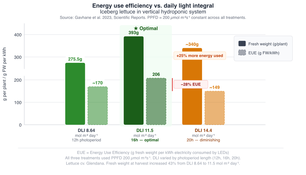 Energy use efficiency versus daily light integral for iceberg lettuce grown at 200 µmol m⁻²s⁻¹ PPFD. The optimal DLI of 11.5 mol m⁻² day⁻¹ (16h photoperiod) produces both the highest fresh weight (393 g) and the highest energy use efficiency (206 g FW/kWh). Increasing to 14.4 mol m⁻² day⁻¹ consumes 25% more electricity while reducing yield and cutting energy use efficiency by 28%.
Research on iceberg lettuce in vertical hydroponic systems found that fresh weight at harvest increased from 275.5 g to 393 g as DLI increased from 8.64 to 11.5 mol m⁻² day⁻¹, a 43% yield increase. However, further increasing DLI to 14.4 mol m⁻² day⁻¹ had a negative impact on fresh weight, dry weight, and leaf area, with energy use efficiency falling by 28%. The optimal DLI represents a genuine economic optimum, not a maximum, and exceeding it wastes electricity while actually reducing crop performance.
This research finding has a direct design implication: vertical farm LED modules should be specified to deliver the crop-specific optimal DLI efficiently, not to maximize PPFD output. A module that delivers 300 µmol m⁻² s⁻¹ when the crop saturates at 200 µmol m⁻² s⁻¹ is wasting 33% of its electrical input, and doing so every hour of every operating day.
Comparative crop efficiency research has also demonstrated that species differ significantly in how efficiently they convert incident light to biomass. Mizuna (Brassica rapa var. japonica) achieves higher dry weight than lettuce at all PPFD levels from 125 µmol m⁻² s⁻¹ upward, has greater projected canopy size, and demonstrates higher light use efficiency (LUE, expressed as grams of dry weight per mole of incident light) at all six PPFD levels tested. For vertical farm operators selecting crops to optimize the return on their lighting electricity cost, species and cultivar light use efficiency is a commercially significant variable.
Module Format Selection: Matching the Module to the Rack Architecture
Lumistrips' analysis of LED lighting systems for plant growth identifies several module formats that are specifically suited to vertical farm applications. Linear LED modules represent two-thirds of the total demand, a dominance that reflects the architectural compatibility of linear formats with the rectilinear geometry of multi-tier rack systems.
Linear LED Bars: The Dominant Format
Linear LED bars, also referred to as TLEDs, are the most common LED module typology worldwide. Their defining characteristic is a slim, lightweight profile that allows them to be placed immediately above the plant canopy in vertical farming systems without releasing excessive radiant heat at close range and without creating structural load issues on lightweight rack systems.
For vertical farm applications, linear LED bars are typically mounted in arrays, with multiple bars running parallel across the full width of the growing tier, and spacing between bars determined by the optical design to achieve the required PPFD uniformity across the tray. The bar-to-bar spacing is a critical design variable: too wide, and PPFD falls significantly in the zones between bars; too narrow, and the cost per unit area increases unnecessarily. The optimal spacing is determined by the beam angle of the LED package and any secondary optic used, the mounting height, and the target uniformity specification.
For growing trays typically 0.5–1.2 m wide under a 16–20-hour photoperiod, Lumistrips can design linear LED bar arrays to achieve min/avg PPFD uniformity ratios of 0.80 or better, meaning no point on the growing surface receives less than 80% of the average PPFD. At typical vertical farm mounting distances, achieving this standard requires careful attention to both bar spacing and optical beam profile.
Multi-Linear and Spider-Style Modules
Multi-linear modules, composed of several linear bars assembled as a unified lighting system, are specifically promoted for multilayer cultivation systems due to their slim profile and suitability for full-cycle cultivation of leafy greens and microgreens. They provide a higher installed power density than single bars, enabling higher PPFD targets from a single mounting point, relevant for crops with higher DLI requirements or where the photoperiod must be shortened for production scheduling reasons.
Spider-style modules, characterized by individual LED clusters spread on radial arms are widely used in controlled-environment agriculture and multi-tier farming. Their geometry allows flexible photon distribution across a growing area from a single mounting structure, an advantage in rack systems where individual module mounting points are at a premium.
Panel LEDs for Cannabis and High-Intensity Applications
Panel LEDs are strongly represented in cannabis cultivation, a crop with significantly higher PPFD requirements (typically 600–1,000+ µmol m⁻² s⁻¹) than leafy greens. For vertical farm cannabis production where inter-tier spacing is larger (typically 0.8–1.2 m clear height) to accommodate plant height, panel formats provide the higher power density needed to achieve target PPFD at greater mounting distances. Chip-on-board (COB) panels, characterized by multiple LED chips within a small area with strong lenses to direct light downward, are a common format for high-intensity applications where compactness and high PPF from a small footprint are design requirements.
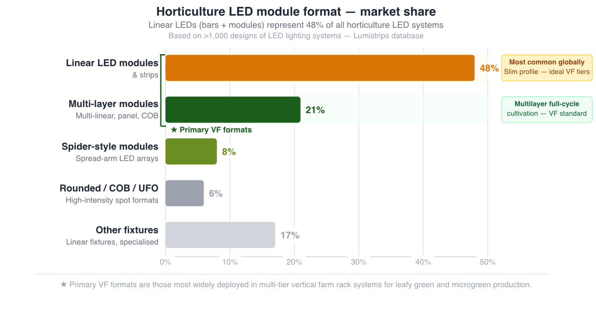
Horticulture LED module format market share from Lumistrips' database of over 1,000 LED lighting system designs. Linear LED modules and strips are the dominant format for vertical farm tier lighting and represent 48% of all horticulture LED systems. Multi-layer module formats promoted specifically for multilayer full-cycle cultivation account for a further 21%.
DLI, PPFD, and Photoperiod: The Lighting Design Triangle
The three variables that determine the total photosynthetic light dose in a vertical farm, DLI, PPFD, and photoperiod, form an interdependent design triangle. Any two values determine the third, and the optimal combination for a given crop is not simply a matter of maximizing all three.
Daily Light Integral (DLI), expressed in mol m⁻² day⁻¹, is the total quantity of photosynthetically active photons delivered to the crop per day. It is the integral of PPFD over the photoperiod. DLI requirements are crop-specific: lettuce targets approximately 11.5 mol m⁻² day⁻¹ for optimal fresh weight and energy use efficiency; microgreens may require 10–12 mol m⁻² day⁻¹; cannabis in the flowering stage may require 40+ mol m⁻² day⁻¹. Operating above the optimal DLI for a crop reduces energy use efficiency without proportional yield gains, and in some crops, actively reduces yield as photodamage begins to exceed the photosynthetic benefit.
PPFD (µmol m⁻² s⁻¹) determines the intensity of instantaneous light delivery. For a fixed DLI target, PPFD and photoperiod are inversely related: high PPFD can deliver the same DLI in a shorter photoperiod, while low PPFD requires a longer photoperiod. Research has consistently shown that plants grown under the same DLI at lower PPFD with extended photoperiod achieve more photosynthetic activity and biomass production than those grown at higher PPFD for shorter periods, a consequence of the diminishing returns in the photosynthesis light response curve at high PPFD. Continuous light (24h photoperiod) has been shown to increase dry and fresh shoot biomass in lettuce under red and blue LEDs, though the effect varies significantly by species and cultivar.
Photoperiod is the duration of the light period per 24-hour cycle. For most leafy greens, 16 hours is the standard commercial photoperiod, providing a balance between DLI delivery and the biological need for a dark period. At 200 µmol m⁻² s⁻¹ PPFD and a 16-hour photoperiod, the DLI delivered is 11.52 mol m⁻² day⁻¹, matching the research-identified optimum for iceberg lettuce. The daily electricity consumption per unit growing area is directly proportional to PPFD × photoperiod duration, making this combination one of the most directly impactful engineering decisions in vertical farm energy management.
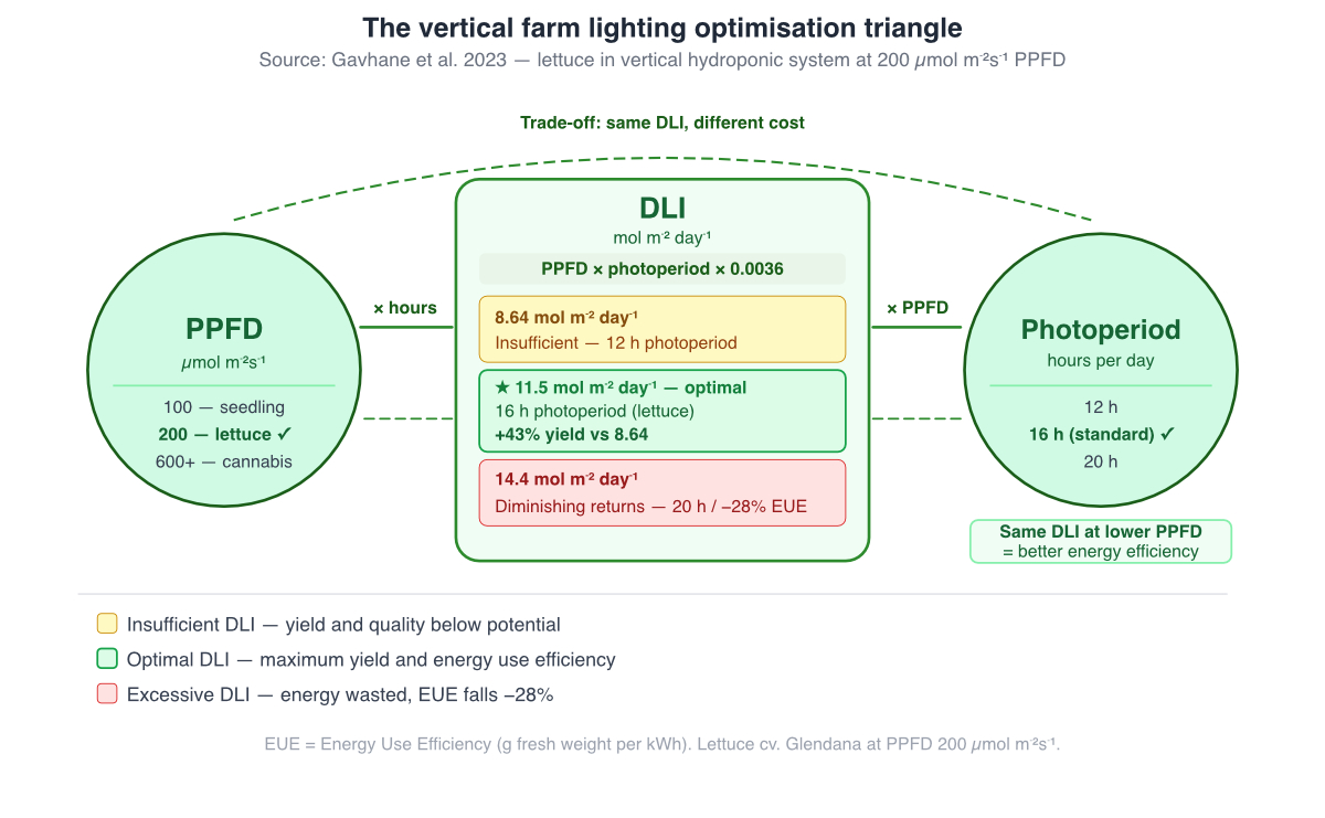
The vertical farm lighting optimization triangle. DLI is the product of PPFD and photoperiod, but the same DLI delivered at lower PPFD over a longer photoperiod typically produces better energy use efficiency. The optimal DLI for iceberg lettuce is 11.5 mol m⁻² day⁻¹: exceeding it costs more electricity while reducing yield and energy use efficiency.
The design decision for a vertical farm LED module system is therefore not simply "what PPFD?" but "what PPFD, over what photoperiod, to deliver what DLI, at what electricity cost per kilogram of product?" This optimization is crop-specific and requires integrating the photobiology data with the economics of the specific operation.
Mounting Distance and Close-Canopy Optical Design
The constraint that most distinguishes vertical farm LED module design from all other horticulture lighting applications is fixed, short mounting distance. In a greenhouse, the lighting designer has freedom to adjust fixture height, fixture spacing, and beam angle to achieve the desired PPFD uniformity. In a vertical farm, the tier height is fixed by the rack structure, and the mounting distance is the residual space between the top of the plant canopy and the underside of the LED module, a dimension that changes as the crop grows.
At mounting distances of 0.15–0.40 m, the following design constraints apply directly:
Hotspot formation: Standard dome-lens LED packages produce a peaked Lambertian emission that creates high-intensity zones directly below each LED and lower-intensity zones between LEDs. At 0.2 m mounting distance, the peak-to-trough variation across a growing tray can be significant if LED spacing is not matched to the emission profile. Cree has LEDs specifically engineered with a close-canopy beam profile that allows mounting up to 40% closer than standard LEDs while maintaining equivalent uniformity, a capability that directly translates into shorter inter-tier spacing and more growing layers per meter of facility height.
End effects: LED strips and bars produce lower PPFD at the ends of each strip than at the center, because the end LEDs have fewer neighboring contributions. At the 0.2–0.4 m distances typical of vertical farm tiers, end effects are proportionally larger than at greenhouse mounting heights and must be compensated for through strip overlap design or strip end optical treatment.
Edge-of-tray variation: Growing trays have defined edges, and photons falling outside the tray perimeter are wasted. The optical design must confine emission to the tray area, a requirement for narrow-angle secondary optics or careful strip layout with minimal overhang.
Lumistrips' approach to vertical farm close-canopy optical design can integrate secondary optics from LEDiL, Carclo, and ARI into LED module designs that address all three constraints.
PCB Substrate and Thermal Management for Vertical Farm Modules
The combination of close mounting distance and high operating hours creates a specific thermal engineering requirement for vertical farm LED modules. At 16–20 hours per day, 300+ operating days per year, vertical farm LED systems accumulate 4,800–6,000 hours of annual operation, among the highest of any horticulture LED application. The thermal design must support this duty cycle while keeping radiant heat emission toward the plant canopy within acceptable limits.
For most vertical farm leafy green applications, operating at 150–250 µmol m⁻² s⁻¹ PPFD from linear LED bars, mid-power LED packages on FR4 PCB substrates provide adequate thermal management when drive currents are kept at 70–80% of rated maximum and the modules are mounted in aluminum channel profiles that provide heat-sinking. The slim profile of FR4-based linear modules is architecturally advantageous in vertical farm tiers where every millimeter of clear height has value.
For higher-power applications, cannabis cultivation at 600+ µmol m⁻² s⁻¹ or multilinear modules with high-power density, aluminum PCB substrates are the correct specification. The aluminum core provides the thermal conductivity needed to maintain junction temperatures within specification under the higher drive currents required for high-PPFD delivery, and the resulting lower thermal resistance directly extends the L80 lifetime of the system under the intensive operating schedule of a commercial vertical farm.
Flexible PI flex LED strips are particularly well-suited to vertical farm applications where strips are deployed in long continuous runs along the tier length. Lumistrips' Reel-to-Reel (R2R) manufacturing produces PI flex strips in reels up to 100 meters in length, with consistent solder joint quality and ±0.1 mm LED placement accuracy across the entire reel, eliminating the interconnect failures that are common in manually assembled flex strip systems deployed at the scale of a large vertical farm installation.
Spectrum and Control: The Operational Levers in Vertical Farms
Spectrum for Sole-Source Vertical Farm Lighting
In a vertical farm, LEDs are the only light source as there is no natural daylight spectrum to complement the artificial system. This means the spectral design must independently provide everything the crop requires from light, across all wavelengths relevant to photosynthesis, morphology, and secondary metabolite production.
For leafy green vertical farms, full-spectrum white LED designs, whether Nichia Hortisolis™, Cree Photophyll™ Select, or Seoul Semiconductor SunLike, provide the photobiology completeness that sole-source lighting demands while also providing the white light environment that allows workers to visually assess crop health during cultivation operations. The worker environment quality argument for full-spectrum LEDs is stronger in vertical farms than in greenhouses: vertical farm workers spend extended time in the growing environment, under LEDs that are the only light source in the room, making the light quality of the grow environment directly relevant to both worker welfare and the accuracy of crop health monitoring.
For cannabis and medicinal plant vertical farms where stage-specific spectral control is a production requirement, multi-channel modules with independent red, blue, far-red, and white channels allow the spectral recipe to be adjusted between vegetative and flowering stages without changing the hardware, a significant operational advantage over fixed-spectrum systems that must be physically reconfigured between production phases.
Smart Control: DLI Optimisation and Energy Management
In a vertical farm with no daylight input, the LED control system's primary function shifts from daylight harvesting (which is relevant in greenhouses) to DLI optimisation, ensuring that the target DLI is delivered to the crop at the lowest possible electricity cost, given time-of-use electricity tariff variation.
Research has demonstrated that optimal supplemental lighting control strategies, formulated as constrained convex optimisation problems, can significantly reduce electricity cost while maintaining crop growth targets. By modelling the relationship between PPFD and photosynthetic electron transport rate (ETR), and integrating electricity price variation across the photoperiod, control systems can schedule LED output to concentrate light delivery during low-tariff periods while staying above the minimum instantaneous PPFD threshold required for photosynthesis. The daily photochemical integral (DPI), the integral of electron transport rate over 24 hours, is a more precise predictor of plant growth than the simpler DLI metric and is increasingly used in research as the basis for lighting optimisation algorithms.
For "Green Towers" lettuce, research identified a minimum DPI of 3 mol m⁻² d⁻¹ (corresponding approximately to a DLI of 17 mol m⁻² d⁻¹ under ambient sunlight conditions) as the growth target. IoT-enabled LED control systems that track DPI accumulation in real time and adjust LED output accordingly can achieve this target at lower electricity cost than constant-PPFD systems by exploiting the diminishing marginal returns of photosynthesis at higher PPFD.
Scalability and Manufacturing Consistency
A vertical farm at commercial scale may deploy thousands of individual LED modules across hundreds of growing tiers. At this scale, manufacturing consistency, the confidence that every module installed at commissioning delivers the same PPFD, the same spectrum, and the same lifetime as every other module in the facility, becomes a system-level production requirement rather than a quality assurance detail.
This is one of the strongest arguments for specifying LED modules from a manufacturer with automated, ISO-certified production rather than manually assembled commodity strips. Lumistrips' SMT production facility in Hechingen, Germany, operates to ISO 9001, 14001, and 45001 standards, with automated pick-and-place and reflow processes that deliver consistent solder joint quality and LED placement accuracy across production runs. For vertical farm projects where thousands of modules must perform identically over a 7–10 year operational life, this manufacturing consistency is as important as the spectral and efficacy specifications of the individual components.
R2R flex production adds a further dimension: the ability to produce the full lighting complement for an entire growing tier as a single continuous strip, eliminating the inter-strip connectors that represent the highest-density failure point in manually assembled systems. For a vertical farm with 500 tiers, each 10 meters long, eliminating inter-strip connectors along each tier translates directly to a reduction in the number of potential failure points across the installation and a corresponding improvement in the facility's long-term operational reliability.
How Lumistrips Approaches Vertical Farm Module Design
Vertical farm LED module design at Lumistrips begins with a conversation about the facility's core economics: the target crop, the electricity tariff, the required production throughput, the available tier height, and the capital budget. From these inputs, we work backward to the LED module specification, the PPFD target, the DLI design point, the spectrum, the module format, the optical design for the specific mounting distance, the PCB substrate, and the control system architecture.
We draw on our database of 20 years of design of LED lighting systems for plant growth, our knowledge base of 100+ quantitative research studies on crop-specific light requirements, and our direct partnerships with Nichia, Cree, Osram, Seoul Semiconductor, and LumiLeds to select LED components matched to the production target. Secondary optics from LEDiL, Carclo, and ARI are specified for each tier height and tray dimension. PCB substrates are selected based on the thermal design requirements of the chosen LED and drive current combination.
The result is a vertical farm LED module specification that is engineered for the economics of the specific facility, not a catalog product applied generically. For operators planning new vertical farm facilities, or upgrading lighting systems in existing ones, this engineering-first approach is the difference between a lighting system that delivers its production plan and one that constrains it.
Planning a vertical farm LED lighting system?
Lumistrips designs and manufactures custom LED modules for vertical farm applications, from leafy green multi-tier systems to cannabis and medicinal plant facilities. Our engineering team works from your facility parameters to a complete LED module specification, including DLI optimisation, close-canopy optical design, and manufacturing to ISO-certified German quality standards. Talk to our vertical farm lighting specialists.
← Back to the series: LED Lighting for Horticulture, The Complete Engineering Guide
Sources: Gavhane et al. (2023), Scientific Reports, Optimal DLI for indoor cultivation of iceberg lettuce in a vertical hydroponic system; Lumistrips Horticulture LED Knowledge Base (1,473 LED system database); ams OSRAM Horticulture LED White Paper (2023); Chaichana et al. (2022), Energy Reports, Modelling of annual sunlight availability on vertical shelves; Agronomy 2024, 14, 55, LED spectrum effects on plant growth; IoT-enabled LED control for greenhouse lettuce, Plants 2021.


